Overview
Xillybus' most common usage scenario is data acquisition. This page shows how to get started with transmitting data from the FPGA to the host.
For a more detailed view on the interaction with Xillybus inside the FPGA, refer to Xillybus FPGA designer's guide.
If the application has a high data rate, it's also recommended to read the guidelines about this in chapter 5 of the Getting Started guide for Linux or for Microsoft Windows.
The host's side
In order to understand how Xillybus works, it's easiest to start from the computer's side: This command can be used to perform data acquisition into a file on the disk:
$ cat /dev/xillybus_read_32 > capture-file.dat
"cat" is a standard Linux command that reads all data from a file and writes this data to standard output. In this example, the input is not a regular file, but a device file. This input consists of a data stream that arrives from the FPGA. There is a redirection of the standard output, so this data is written to a file on the disk.
This is not an artificial example: In some usage scenarios, this is the correct way to practically use Xillybus for data acquisition. It may be better to use "dd" in order to obtain a specific amount of data. More often, a dedicated computer program is used to read the data from the device file. Each application has its own preferred way to consume the data.
So it doesn't matter which programming language you prefer, or if you use Linux or Windows. The computer software that receives the data from the FPGA only needs to do the same as "cat": Open a file, and read from it. There is a separate page that introduces the standard programming techniques for file I/O. Even more detailed information about programming techniques with Xillybus can be found in the programming guides for Linux and Windows.
The logic for data acquisition
Now let's see what happens in the FPGA. The Xillybus IP core and the application logic interact through a FIFO: The application logic writes data into the FIFO, and Xillybus makes sure that this data reaches the host. There is a separate page that explains how FIFOs work, if you're not familiar with this concept.
Xillybus' demo bundle contains a file named xillydemo.v. This is the Verilog code that interfaces with the IP core. There is also a VHDL file in the demo bundle: xillydemo.vhd. However, the example below is in Verilog.
The Xillybus IP core's instantiation takes place in xillydemo.v. (or xillydemo.vhd). These are the parts that are relevant to the data acquisition example with the "cat" command from above (the other parts are skipped).
   // Wires related to /dev/xillybus_read_32
   wire        user_r_read_32_rden;
   wire        user_r_read_32_empty;
   wire [31:0] user_r_read_32_data;
   wire        user_r_read_32_eof;
   wire        user_r_read_32_open;

[ ... ]

   xillybus xillybus_ins (
[ ... ]
			  // Ports related to /dev/xillybus_read_32
			  // FPGA to CPU signals:
			  .user_r_read_32_rden(user_r_read_32_rden),
			  .user_r_read_32_empty(user_r_read_32_empty),
			  .user_r_read_32_data(user_r_read_32_data),
			  .user_r_read_32_eof(user_r_read_32_eof),
			  .user_r_read_32_open(user_r_read_32_open),
[ ... ]
			  .bus_clk(bus_clk),
[ ... ]
			  );
The meaning of the IP core's ports is described in detail in Xillybus' guide to the logic API.
There is an instantiation of a FIFO in xillydemo.v. This FIFO is a single-clock FIFO, which is suitable for the loopback that is demonstrated in the original Verilog code. For a data acquisition application, a dual-clock FIFO is more suitable, because the data acquisition logic usually relies on its own clock.
So you can change xillydemo.v into a module that performs data acquisition as follows: Delete the instantiation of the single-clock FIFO (it's called fifo_32x512). Insert this instead:
   assign user_r_read_32_eof = 0;

   dualclock_fifo_32 fifo_32
     (
      .rd_clk(bus_clk),

      .rst(!user_r_read_32_open),
      .rd_en(user_r_read_32_rden),
      .dout(user_r_read_32_data),
      .empty(user_r_read_32_empty)

      .wr_clk(capture_clk),

      .wr_en(capture_en),
      .din(capture_data),
      .full(capture_full)
      );
The dual-clock FIFO
dualclock_fifo_32 is a standard dual-clock FIFO. It needs to be created as an IP with the FPGA's development software. The depth of this FIFO should be 512 elements or more. Due to differences between FPGA software, the names of the ports may be different than shown above. It should nevertheless be easy to deduce how to connect the FIFO's ports.
Once again, there is a page that introduces FIFOs, if you're not familiar with them already.
Several of the FIFO's ports are connected directly to Xillybus' IP core: @rd_clk, @rd_en, @dout and @empty. Note that these connections are made exactly the same as in the demo bundle. The IP core uses these four signals to pull data from the FIFO. This is always the correct way to connect these ports with the IP core.
Note that @rd_clk is connected to @bus_clk. This signal comes from Xillybus' IP core. In other words, the IP core dictates the clock that is used by one of the FIFO's sides.
As for @rst, note that it is connected to !user_r_read_32_open. @user_r_read_32_open is high only when the related device file is open on the host. As a result, the FIFO is reset when the file is not open. Hence the FIFO is empty when the host opens the device file: If there were leftovers in the FIFO's storage from a previous session, they were deleted when the device file was closed.
This behavior is what we usually expect from a source of data. But if you want the FIFO to retain its data when the device file is closed, connect something else to @rst. Or possibly hold @rst low.
Note that @user_r_read_32_eof is zero in this example, as well as in the demo bundle. This signal can be used to send an end-of-file to the host. More about this in the guide to the API.
Interface with the application logic
In a data acquisition application, there is always some kind of application logic that produces data for transmission to the host. This part is different from one application to another, and is hence irrelevant to this discussion. We shall focus on sending this data to the host.
This part is surprisingly easy: The application logic writes this data to the FIFO. The data that is written to the FIFO arrives to the computer program on the host as a contiguous data stream.
Accordingly, the application logic uses the standard convention for writing to a FIFO. In the example above, this is shown with @capture_clk, @capture_en, @capture_data and @capture_full. This logic only needs to put the data in @capture_data and control @capture_en in order to correctly write to the FIFO. Note that the application logic uses its own clock for writing to the FIFO.
The data flow
This is a simplified block diagram that illustrates the data flow from the application logic to the user application program on the host.
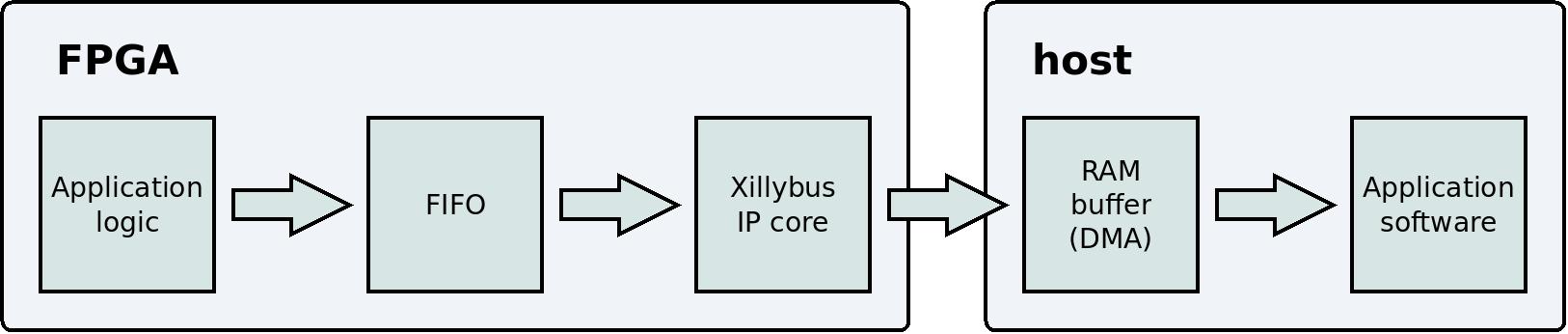
Note that two technical details have been omitted from this block diagram: The PCIe block and the kernel driver are not shown, because they are irrelevant to the user's perception of the data flow. The correct way to use Xillybus is to forget about these details, and focus on the application logic and the application software.
There is no need to organize the data into packets: The communication channel between the application logic and the computer is a continuous stream. The IP core and the driver ensure that the data flow behaves like other stream protocols, e.g. pipes between programs in Linux. Another protocol with similar behavior is TCP/IP. In other words, it doesn't matter how much data is written to the FIFO. This data will soon reach the user application program on the host.
It's a common mistake to organize the data into packets and adapt the IP core's DMA buffers to the size of these packets. There is no advantage in doing this. Even if the data is sent in packets that have a constant size, there is no need to adapt the IP core to this size.
But what if the FIFO becomes full?
One of the basic rules about a FIFO is: If the @full port is high, @wr_en must be low. In simple words: Don't write to a full FIFO. So what if that happens? Handling this situation would complicate the application logic considerably.
The short answer is that the FIFO should never become full: Under normal operation conditions, this is prevented actively: The IP core reads data from the FIFO and copies this data into the host's RAM. This happens quickly enough to prevent the FIFO from filling. Usually, the FIFO doesn't need to be deeper than 512 data elements.
However, the FIFO may become full if the application logic writes to the FIFO too rapidly. In other words, if the application logic's average data rate exceeds the IP core's limit (as advertised for each type of IP core), the IP core will not be able to read the data quickly enough from the FIFO.
Another possibility is that the user application software (e.g. "cat" in the example above) doesn't read the data quickly enough from the device file. As a result, the RAM buffer at the host will become full, and this too will prevent the IP core from reading from the FIFO (because the IP core won't have anywhere to write the data to). As a result, an overflow occurs. This can happen because the user application software is written badly. Another possible reason is related to the operating system, which is discussed further below.
The size of the RAM buffer on the host depends on the Xillybus IP Core. For example, this size is 4 MBytes for xillybus_read_32 and xillybus_write_32 (in the IP core that is part of the demo bundle). The IP Core Factory allows creating custom IP cores that request significantly larger buffers.
In conclusion: Preventing an overflow is a matter of choosing the correct parameters for the IP core: First and foremost, this IP core should be capable of handling the data rate. In addition to that, the host's RAM buffer should be large enough. This ensures that the data flow can continue even while the user application program doesn't read data from the device file.
If the FIFO becomes full despite all this, the common reason is a mistake in the system design. A common reason for an overflow is an overestimation of the computer's capability to handle the data rate.
In particular, if the data is written to a file on the disk (as with the "cat" command above), the maximal data rate can be slower than one thinks. The reason is that the operating system often has a large disk cache (possibly many Gigabytes). If the disk's data rate is measured with an amount of data that is smaller than the disk cache, the results will be too optimistic: The operating system will pretend to have finished writing the data to the disk before this has actually happened. In reality, the data only reaches the cache, and the actual writing to the disk happens later. This mistake will be revealed only when a larger amount of data is handled.
Deprivation of the CPU
Unfortunately, there is an inevitable possibility for an overflow: The operating system (Linux or Windows) is allowed to deprive any user-space process of the CPU for an unlimited amount of time. In other words, the computer program that reads the data can suddenly stop working for a period of time, and then resume normal operation. There is no limitation on this time period. Any non-real-time operating system is allowed to randomly pause processes like this.
And yet, data acquisition is still possible with these operation systems. This is mainly because a long deprivation of the CPU is considered a bad trait in general. So these pauses are usually short.
During these pauses, the IP core continues to fill the RAM buffer on the host (by virtue of DMA, so the processor's intervention is not required). When the computer program gets the CPU back, it can quickly consume all data that has been accumulated. A RAM buffer that compensates for a 10 ms pause is usually enough. However, it's possible to request a significantly larger buffer when creating a custom IP core at the IP Core Factory.
That said, there is still a possibility that the pause will be too long. As a result, the RAM buffer will become full, and consequently the FIFO on the FPGA will become full. The result of this overflow is that data will be lost. This should never happen, and it will probably never happen. But what if it does?
Detecting an overflow
The suggested solution is to put an end to the data stream if the FIFO becomes full: The logic sends an EOF (end-of-file) to the host immediately after the last element of contiguous data. So let's consider what happens if the host consumes the data with a "cat" command, as suggested above:
$ cat /dev/xillybus_read_32 > capture-file.dat
Normally, this command will continue until it's stopped with a CTRL-C. But if the FIFO became full in the FPGA, this command will terminate normally, just like it would do after finishing to copying a regular file. The output file will contain all data that was collected before the FIFO became full.
To summarize this method: All data that is written to capture-file.dat is guaranteed to be error-free and contiguous. If the data acquisition system fails to maintain the continuity because of a CPU deprivation, the result is a shorter output file. But the content of the file can be relied upon.
In order to implement this solution, replace dualclock_fifo_32's instantiation with this:
   eof_fifo fifo_32
     (
      .rd_clk(bus_clk),

      .rst(!user_r_read_32_open),
      .rd_en(user_r_read_32_rden),
      .dout(user_r_read_32_data),
      .empty(user_r_read_32_empty)

      .wr_clk(capture_clk),

      .wr_en(capture_en),
      .din(capture_data),
      .full(),
      .eof(user_r_read_32_eof)
      );
The definition of eof_fifo is given on a separate page.
Note that @user_r_read_32_eof is connected to this FIFO's @eof port. This is how the logic sends the EOF to the host when necessary. Also note that nothing is connected to this FIFO's @full port: There is no need to monitor this signal anymore. If the FIFO gets full, there is not much to do about it. The EOF mechanism makes sure that the host restarts the data flow after all valid data has been consumed.
Data playback
What about the opposite direction? What about something like this?
$ cat playback-data.dat > /dev/xillybus_write_32
This works by the same principle: The "cat" command reads from a file on the disk and writes the data into a device file. On the FPGA, the IP core writes this data into a FIFO. The application logic reads the data from the FIFO. Same idea, only in the reverse direction.
This is a simplified block diagram that illustrates the data flow from the user application program on the host to the application logic.
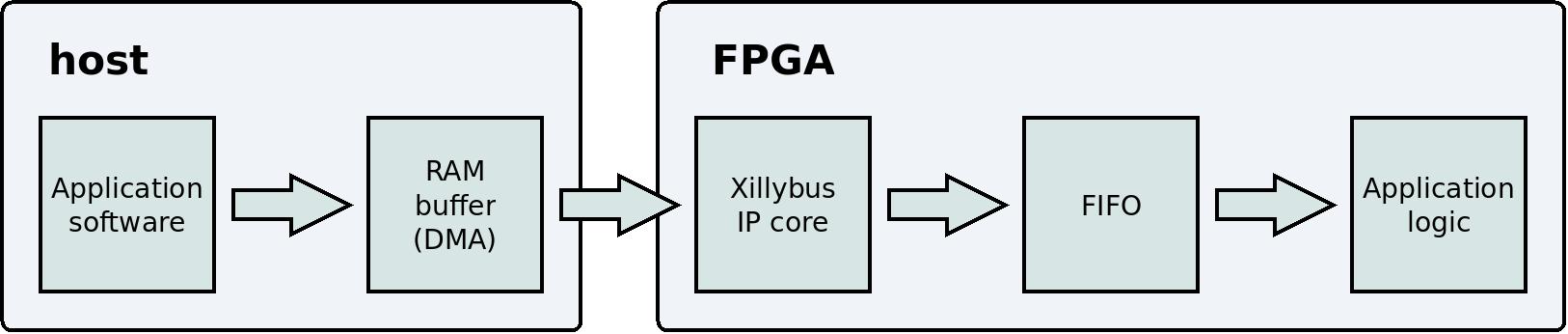
Similar to data acquisition, there is no risk for a loss of data: The IP core doesn't write to the FIFO when it is full. As a result, the buffer in the host's RAM may become full as well. When this happens, the user application program on the host waits (by sleeping) until the application logic reads enough data from the FIFO.
Another similarity with data acquisition is that the FIFO will never become empty as long as the user application program continues to write data rapidly enough. In order to guarantee this, the same considerations are relevant: The IP core's specification as well as the user application program must support the required data rate.
When these conditions are met, the application logic can consume data from the FIFO when this data is needed. An underflow should never happen.
Asynchronous streams vs. Synchronous streams
This topic is not directly related, but it's still worth a brief discussion.
In a data acquisition application, the primary goal is to maintain a continuous data flow. Accordingly, the IP core moves the data from the FIFO to the host's RAM buffer as soon as possible. It doesn't matter if the user application program on the host is requesting the data at the given moment (by virtue of a function call to read() or alike): The data flow continues as long as the device file is open and there is data in the FIFO.
This means that the host has no way to control the data flow from the FPGA (except for opening and closing the device file, or resorting to an application-specific solution). However, in most real-life data acquisition applications, there is no need to control the data flow: It's fine that the data flow begins as a result of opening the device file. It's not important exactly when the each element of data was read from the FIFO.
A device file that behaves like this is called an asynchronous stream (in Xillybus' terminology).
However, in other applications it is important when the data was collected. For example, the application logic on the FPGA may send the content of a status register instead of data from a FIFO. This is demonstrated in the demo bundle with the device file named xillybus_mem_8. In this case, it is very important to control when the data is collected at the FPGA: The host reads from the device file in order to obtain information about the status at that moment, and not what the status was at some unknown time in the past.
Xillybus has synchronous streams for applications of this sort: The IP core always collects as little data as possible from the FPGA. In other words, the IP core collects data only in response to a function call to read() (or alike) on the host. Hence the host controls when the data is collected from the FPGA.
The disadvantage of synchronous streams is the pauses in the data flow. The main problem with these pauses is that the FIFO on the FPGA can become full when the data flow is momentarily halted. These pauses also reduce the efficiency of the data flow, so the maximal data rate becomes lower. However, these two disadvantages are relevant only for a data acquisition application. Such an application should use an asynchronous stream anyhow.
Regarding device files in the opposite direction, there is also a difference between asynchronous streams and synchronous streams. In this direction, the difference is in the return of the write() function call: With an asynchronous streams, write() returns as soon as the data has been written to the RAM buffer. So in most cases, write() doesn't sleep at all. With synchronous streams, on the other hand, write() waits until the data has been delivered at the FPGA. This is important when the communication channel is used to send commands. But once again, this is bad for a data acquisition application.
In the demo bundle, only /dev/xillybus_mem_8 is a synchronous stream. The other four device files are asynchronous streams.
In the IP Core Factory, the choice between a synchronous stream or an asynchronous streams depends on the selection of application (the drop-down menu for "use"). For example, if you choose "Data acquisition / playback", the tool produces an asynchronous streams. If you choose "Command and status", you get a synchronous stream. It's also possible to select this manually, by turning off "Autoset internals".
For more information about asynchronous streams and synchronous streams, refer to section 2 in the programming guide for Linux (or the programming guide for Windows). Regarding the IP Core Factory, refer to the guide to defining a custom Xillybus IP core.
Summary
A simple, and yet practically functional data acquisition system can be created simply and quickly with Xillybus: The application software boils down to using a standard Linux command ("cat"). On the FPGA's side, the interaction with Xillybus' IP core merely consists of writing the data to a FIFO.
The data that is collected with Xillybus is guaranteed to be error-free and contiguous. However, due to the operating system's nature, there is no way to guarantee that an overflow will never occur. As this is inevitable, the optimal approach is to guarantee the detection of an overflow if it happens. Xillybus offers a simple mechanism for this purpose, by virtue of sending an EOF to the host.