Scope
This page is the second in a series of five pages about FIFOs. After presenting the basics of a FIFO in the previous page, it's time to discuss common variants and extra features. FIFO are often configured as a combination of the options that are described below.
Single clock FIFOs
Even though the "baseline FIFO" has two inputs for unrelated clocks, it's often the case that the signals at both sides are synchronous with the same clock. It's perfectly fine to connect this same clock to @wr_clk and @rd_clk. But since it's the same clock on both clock inputs, there is no need to for a clock domain crossing, so the FIFO contains unnecessary logic. More about clock domains can be found here.
So every FPGA vendor offers two categories for a FIFO: Dual-clock FIFO and single-clock FIFO. Other names are often used: Independent Clock FIFO vs. Common Clock FIFO or Asynchronous FIFO vs. Synchronous FIFO. The "baseline FIFO" that was presented on the previous page is a dual-clock FIFO.
Single-clock FIFOs don't have any synchronization logic, as all logic is synchronous with the same clock. Hence the reset input must be synchronous with the same clock as the other ports.
Except for not wasting FPGA logic, the other good reason to use single clock FIFOs is for clarity. It's a way to state loud and clear that there's no intention to have two clocks involved.
In short: If the FIFO doesn't connect between two clock domains, go for a single-clock FIFO.
FWFT FIFOs
As emphasized in the previous page, the procedure for reading data from a "baseline FIFO" is to change @rd_en to high and obtain the value on the FIFO's @dout output on the next clock cycle. That's somewhat counterintuitive: If the data is already in the FIFO, why do I have to ask for it? Why can't the FIFO just put it on the @dout port, and tell me that it's fine to use it?
So there's a common variant doing exactly that, and it's called a First Word Fall Through FIFO (FWFT, sometimes also called read-ahead, show-ahead or look-ahead). The opposite of a FWFT FIFO is often referred to as a "Standard FIFO" (can someone show me the standard?).
The idea is simple: When an FWFT FIFO stops being empty (because data was written to it), it presents the first word on @dout. The application logic then reads words by holding @rd_en high. The difference is hence just regarding the first word.
It's however easier to understand an FWFT FIFO by realizing that the meaning of two of its ports has changed: @rd_en on a FWFT FIFO actually means "I have just consumed the data on @dout, it's fine to bring the next one" and @empty actually means "@dout is not valid".
What hasn't changed, is that @rd_en should not be high if @empty is high. You can't say that you've consumed invalid data. So the rule remains the same, for a different reason.
The following waveform shows what reading from a FWFT FIFO can look like:
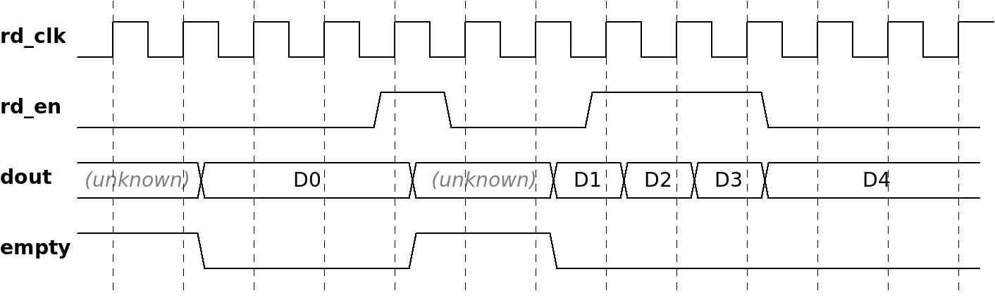
Note that the first valid value at @dout appears while @rd_en is low, and that @empty changes to low at the same time as the valid value appears. As just mentioned, @empty means "@dout not valid" on an FWFT FIFO, and the waveform reflects that.
Also note that the first pulse of @rd_en didn't read a new value from the FIFO, but rather caused @empty to change to high again. Accordingly, the value of @dout became unknown at the same time. In reality, @dout usually doesn't change when @empty changes to high, but you can't rely on that.
After this, the FIFO once again puts a value on @dout and changes @empty to low. The application logic reads three words, and then changes @rd_en to low. All in all, the application logic consumed four or five words from the FIFO.
Note that the waveform doesn't tell us if the application logic used the value of D4 as well. It might have ignored the fifth word, which means it only consumed four words. Or it might have used the value of the fifth word. The only thing that is clear from the waveform is that the application logic held @rd_en low after four clock cycles, so it didn't allow the FIFO to continue to update @dout.
Another thing to note is that we don't know if there is more data inside the FIFO's memory. The fact that @empty is low at the end of this waveform only means that @dout is valid.
Now let's modify the Verilog example from the previous page. Once again, this code calculates the cumulative sum of everything that comes out of the FIFO:
assign rd_en = !empty; // If @dout's value is valid, it's consumed.

always @(posedge rd_clk)
  if (!empty) // FIFO is FWFT, so !empty means @dout contains valid data
    sum <= sum + dout; // Don't try this at home: @sum is never reset.
Unlike the previous example, this one uses a FWFT FIFO, so there's no need for a register that has the value of @rd_en on the previous clock cycle. Instead, @dout can be consumed when @empty is low. This simple rule works because @rd_en is high when @empty is low, so each word from the FIFO is valid on @dout for exactly one clock cycle.
I'd just like to wrap up the FWFT topic with a somewhat unrelated point. The difference between the "standard" FIFO and FWFT FIFO echoes a fundamental issue regarding the data flow between any two modules of logic: Does the receiving side need to ask for the data? Or does the sending side present the data as soon as possible, and the receiving side only confirms it's OK to go on? Always ask yourself this question when one module passes data to another, and in particular ask yourself if these modules agree on this matter.
Asymmetric FIFOs
It's commonly allowed to define the FIFO with different widths for @din and @dout. This is useful, for example, if data arrives to the FPGA in 32-bit words, but the application logic processes them as bytes, that is 8 bits per word. In this case, set the write side's width to 32 bit and the read side's width to 8 bits. Both sides behave as usual, except that it takes four read cycles to consume a word that was inserted with a single write cycle.
When the reading side is wider than the writing side, it behaves as one would expect: The data that is written to the FIFO isn't available at the reading side until the written data has filled a word that is of the size of the reading side.
As for in which order the words are packed, it seems like all FIFOs use Little Endian. For example, a FIFO packs 32 bit words into 8 bit words as follows: The range of bits in the first word that is read from the FIFO is [7:0], and then [15:8], [23:16] and [31:24].
But if you want to use this feature, always check the documentation.
Dependency with combinatorial logic on @empty and @full
The @empty and @full ports have a drawback in common: The application logic has to responds to them on the same clock cycle. In other words, @rd_en must be a combinatorial function that depends on @empty in order to ensure that these two signals aren't high on the same clock cycle (this is forbidden, as already mentioned). By the same coin, @wr_en must be a combinatorial function that depends on @full.
The use of combinatorial functions may become an obstacle in achieving timing constraints. This can become a problem when the clock's frequency is high (relative to what the FPGA's specification) and when the logic function is complicated. The main reason for problems is that both @rd_en and @wr_en are often used in the logic that produces or consumes the data. In particular, the logic function that calculates the clock enable for a lot of logic can depend on these signals. For example, if there is a long pipeline that processes data that comes from a FIFO, all logic in the pipeline must freeze when the data flow from the FIFO stops momentarily.
Well, to be completely accurate, there's a way to avoid that combinatorial function. For example, suppose @wr_en is declared as a register, and @want_to_write is a signal that represents the application logic's need to write at a given time. This can be done:
always @(posedge wr_clk)
  wr_en <= want_to_write && !wr_en && !full;
This ensures that @wr_en and @full are never high on the same clock cycle, because @full can change to high only on the clock cycle after @wr_en was high. The !wr_en part in the expression ensures that @wr_en is never high during two consecutive clocks cycles. So if @full changes to high, @wr_en will be low because of !wr_en on the first clock cycle. @wr_en then remains low because of @full itself.
But with this solution, @wr_en must be low during half the time. As a result, only 50% of the FIFO's data rate is used. This is usually unacceptable.
The same solution is possible for @rd_en, and this solution has the same problem with using half the data rate.
This discussion was intended to lead to the next section: The "almost" ports.
Almost full, almost empty and similar ports
It's possible to add two optional ports to a FIFO: @almost_full port and/or @almost_empty port.
@almost_empty is synchronous with by @rd_clk, and is similar to @empty, but with a small difference: @almost_empty is high when the FIFO is empty, but also when there's exactly one word to read from the FIFO.
Likewise, @almost_full is synchronous with @wr_clk, and is high when the FIFO is full, but also when it's OK to write exactly one word to the FIFO.
The names of these two output ports depend on the FPGA vendor and the software it supplies, but there's always a possibility to add ports with the same functionality. Only sometimes, a certain variant of a FIFO may not support these ports.
How does these ports help? Well, because this works perfectly fine:
always @(posedge wr_clk)
  wr_en <= want_to_write && !almost_full;
No combinatorial logic, and no need to skip half of the write cycles. When @almost_full is high, @wr_en may not change to low on the same clock cycle, but only on the next one. As a result, there can be one write operation after @almost_full changes to high. But that's fine, as there is place for one word.
Note that if @want_to_write is held high continuously while the FIFO is filled, the last write operation fills the FIFO completely. Otherwise, it's possible that the FIFO ends up almost filled: If @wr_en is low because of @want_to_write, and the FIFO doesn't get completely full because of that, there will be no second chance. @almost_full will change to low only when the other side reads data from the FIFO, so there is space for two or more words in the FIFO.
That rarely matters, but for the sake of discussion, this ensures that the last word is used:
always @(posedge wr_clk)
  wr_en <= want_to_write && (!almost_full || (!full && !wr_en));
This expression for @wr_en relies on @almost_full most of the time, except for when it's fine to write exactly one word. Only then, @wr_en depends on @full and the @wr_en, similar to the previous expression above that used !wr_en.
However I seriously doubt if this last expression of @wr_en is useful.
The story with @almost_empty is similar, so this is OK (but don't copy this into your code):
always @(posedge rd_clk)
  rd_en <= want_to_read && !almost_empty;
As with @almost_full, there's an issue with the last word: If @rd_en is low because of @want_to_read, it loses the chance until the FIFO gets filled with more data. Unlike the case with @almost_full, this can definitely be a problem in some scenarios: If @almost_empty is high but the FIFO isn't empty, it means that there's data in the FIFO that was intended for reading, but this data remains stuck in the FIFO.
So this is the safe way to go:
always @(posedge rd_clk)
  rd_en <= want_to_read && (!almost_empty || (!empty && !rd_en));
Fill counters
Application logic often performs operations in chunks. For example, logic that reads packets of data with a constant length from the FIFO and transmits these packets across some physical media. Since the data is stored on a FIFO, the application logic needs to know that there's enough data to fill a packet before it starts reading.
Likewise, application logic often produces a fixed amount of data for storage in a FIFO, e.g. reading a burst of data from external memory. The operation shouldn't start unless there's enough place in the FIFO to complete the burst.
For these purposes, FIFOs usually support fill counters, a programmable empty port and a programmable full port. The fill counters (sometimes called data counters) come in different forms and shapes, much depending on the FPGA vendor, so read the FIFO's documentation carefully. There are three main issues to pay attention to:
- Which clock is the counter synchronous with? Almost needless to say, it has to be the same clock as the logic that uses the counter.
- What does the counter tell us? "Read counters" usually indicate the number of words that are stored in the FIFO, but what about "write counters"? Is it the number of words stored too, or the number of words that can be written until the FIFO gets full?
- What does the counter guarantee? Fill counters are usually pessimistic with relation to their intended purpose. For example, it's common that "read counters" are allowed to temporarily give a lower number than the actual number of words in the FIFO. This occurs while words are written to the FIFO, because these counters increment their value late in response to write operations, but decrement their value early in response to read operations. This makes sense for their use with logic that controls @rd_en, however if a counter of this sort is used by logic that controls @wr_en, you might cause an overflow. For that purpose, there are "write counters". Nevertheless, do read the fine details in the documentation.
In addition, there are programmable empty and programmable full, which are extended versions of @almost_empty and @almost_full. The idea is that because the use of fill counters is almost certainly something like
assign dont_start_reading = (rd_data_count < 64);
why not offer that signal directly, and call it prog_empty? Once again, read the FIFO's documentation carefully.
Once again, when it's important to read the last word in the FIFO, be sure to ask yourself if your logic will indeed do so. This question is similar to the discussion above about @almost_empty.
Almost needless to say, you'll have to request these extra ports when configuring the FIFO, if you want them.
AXI interface
This topic isn't directly related, however it's worth mentioning to avoid confusion, as this term often appears in context of FIFOs.
AXI is set of interfaces defined in the AMBA standard, which was introduced by ARM. As one might expect, FIFOs with AXI interface are usually intended to work as a peripheral to a CPU.
The interface of the "baseline FIFO" is often referred to as "native" interface, as opposed to an AXI interface.
There are two main types of AXI interfaces: The "regular" AXI (typically AXI3, AXI4 or AXI Lite) which is a bus with address and data. The second type, AXI-S (streamed AXI), is intended for streams of data (possibly divided into packets).
When a FIFO is configured as AXI3 / AXI4 or AXI Lite, extra logic is added to it so it can be connected as a peripheral with an address to a CPU through this interface. I won't elaborate on this further, because it's a completely different topic.
But because the streaming interface is somewhat similar to the behavior of a FIFO, it's possible to convert the handshake signals of the AXI-S interface into a "native" one. Note that AXI-S often involves other signals that need tending to as well.
So given the AXI-S signals for writing to the FIFO as @axi_w_valid, @axi_w_ready and @axi_w_data, they can be connected to the ports of a "standard" FIFO with
assign axi_w_ready = !full;
assign wr_en = axi_w_valid && axi_w_ready;
assign din = axi_w_data;
Likewise, the AXI-S signals for reading from the FIFO, @axi_r_valid, @axi_r_ready and @axi_r_data, can be connected to the ports of a FWFT FIFO with
assign axi_r_valid = !empty; // Non-empty means valid with FWFT FIFOs
assign rd_en = axi_r_valid && axi_r_ready;
assign axi_r_data = dout;
Once again, note that for this to work, the FIFO must be a FWFT variant.
This wraps up the second page in this series about FIFOs. The next page shows how a single-clock FIFO is implemented in Verilog.